Free Electronic Circuits,Schematic Diagram,Circuit Diagrams

Thumbnail image that says sleek button using photoshop that links to a Photoshop tutoril. free, electronic circuit, circuit diagram, circuit schematic, schematic diagram, electronic diagram, audio, amplifier, power supply, guitar effect, current loop, current limiter, video, receiver, transmitter, transceiver, transistor, radio frequency, rf, active filters, digital, analog circuit, pwm, micro controller Free download

Free Electronic Circuits,Schematic Diagram,Circuit Diagrams

External links - Jqueryelectronics circuit,circuits,schematic diagram,circuit design,circuit diagram, circuit

Electronic Circuit,Schematic Diagram,Circuit Diagrams

External links - Jqueryelectronic circuit, circuit diagram, circuit schematic, schematic diagram, electronic diagram, audio, amplifier, power supply, guitar effect, current loop, current limiter, video, receiver, transmitter, transceiver, transistor, radio frequency, rf, active filters, digital, analog circuit, pwm, micro controller Free download

Best Song Lyrics Collection

External links - JqueryFind The Music Lyrics To Any Song! It's Free DAILY UPDATED! One of the largest,most accurate, browsable and searchable song lyrics source on the net. lyric, lyrics, song, music, song lyrics, music lyrics

Showing posts with label motor. Show all posts

Wednesday, June 10, 2015

Automatic Fan (DC)


At present we can see the temperature of this planet is increasing day by day so that the people use various types of things to overcome that matter some rich countries use air conditioners but poor countries cant use ac machines because they have to pay unbearable electricity bill.you all know Free Circuit Diagrams 4U always think about all the nations ,all the ages etc. we always try to be balance when we post something that is why we have come to this level.OK, Today we are going to give you a Automatic fan circuit .That means you can operate this circuit with 6V to 12V power.The special thing of this circuit is this circuit is switched on and off according to the temperature of the environment.Here we have used LM35 as the temperature sense sensor and BC 548 to  amplify the current.
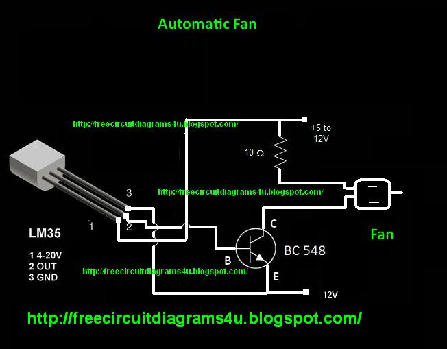


Note : Build this circuit on a PCB


Monday, September 02, 2013

Pulse moter circuit diagram

This is a simple pulse motor circuit diagram.you can use this circuit to power up pulse moters.Here I have used very common IC NE555 you can control the speed of the mortar by adjusting When you use this circuit don't supply over 12V.  

Sunday, January 24, 2010

How to make a simple motor


This is a simple moter circuit.These pictures show how to make a simple motor.first of all you should take two plates that I have mentioned bellow.and set it up on a wooden plate as picture 3 has shown.Then after take coils and wrap it around the plastic stick. When the stick rotates the coil should have a contact with the current supplier so after wrapping place the coil as picture shows.place a magnet middle of the stick as picture shows.

Thursday, January 21, 2010

Temperature controlled fan Circuit diagram


This is temperature controlled fan circuit.When you use this circuit you don't want to turn the switches when the heat goes up.It is controlled automatically.

Wednesday, January 06, 2010

PWM Speed Motor Controller


This is very useful circuit.When we use high speed moters(Pwm)We need a circuit to boost the speed so this is the circuit for it.This circuit can generate 170-200Hz frequency.This circuit operates with 4.5V to 6V.

Saturday, September 12, 2009

PWM Motor Speed Control Circuit

Here is a simple PWM motor speed controller circuit that can be used for varying the speed of low power DC motors .The variation in speed is achieved by varying the duty cycle of the pulse supplied to drive the motor.Of the two gates of IC CD40106B ,N1 is wired as an inverting Schmitt Trigger astable multi vibrator for producing pulses and N2 as an inverting buffer to drive the transistor during positive cycles at base.The duty cycle is set from resistor R2. R1 limits the base current of transistor SL 100.The circuit is ideal for controlling toy motors,hand held mini fans , small blowers etc.


Notes .

* By varying R2 duty cycle can be varied from 0% to 100%.
* For identifying pins of SL 100 ,the pin that is connected to casing is collector,the pin near to notch is emitter and the one remaining is base.

Bi-directional motor

This is a simple and easy to construct circuit that can be used to provide a bidirectional drive to a DC motor. The circuit operation is straight forward. Output of an astable mutivibrator based on IC1 (NE555) is used to control the relay RL1 driving the motor. The motor is connected between the two poles of the relay contacts. The relay contacts are so wired as to reverse the DC supply to the motor when the contacts changeover.


The astable multivibrator produces a square wave at the output with its high time given by 0.69(R1+R3+R5)C1 and low time given by 0.69(R1+R2+R4)C1.The high and low times can be varied by varying potentiometers R4 and R5.For the given values the high and low times can be adjusted between 1S and 8S separately. When the IC1 output is low, the relay is de energised and the relay contacts are in position 1-1 with the result that A terminal of the motor is positive and motor runs in one direction. The IC1 output is high the relay is energised and the contacts changeover to position 2-2.Now the terminal B of the motor becomes positive and motor runs in the opposite direction. The transistor Q1 is used to drive the relay according to the output from IC1.The diode D4 acts as freewheeling diode.


Notes.

* Assemble the circuit on a good quality PCB.
* The circuit can be powered from a 12V DC power supply.
* The IC1 must be mounted on a holder.
* The capacitor C1 must be rated at least 15V.
* The relay RL1 can be a 12V DPDT relay.

PWM motor speed controller


This circuit is designed as per a request made by Mr Vinoth from India. His requirement was a 12V/5A DC fan motor controller. I think this circuit is sufficient for this purpose. Quad 2 input Schmitt trigger IC CD4093 is the heart of this circuit. Out of the four Schmitt triggers inside the 4093, U1a is wired as an oscillator with adjustable duty cycle. The U1b, U1c, U1d buffers the output of the oscillator to drive the switching MOSFET Q1.The MOSFET drives the DC motor according to the switching pulse obtained from the oscillator. When R1 is varied the duty cycle varies and so do the speed of the motor. Diode D3 acts as a freewheeling diode.


Notes.

* Assemble the circuit on a good quality PCB.
* IC U1 should be mounted on a holder.
* U1a, U1b, U1c, U1d are part of the same IC CD4093; so power supply is shown connected only once.
* The12V power supply for this circuit must be able to handle at least 5A.
* A heat sink is recommended for Q1.


.
.
.
.
.
 

Thank U & Come Again.....


Search Engine Optimization and SEO Tools
Submit ExpressSearch Engine Marketing

FREE CIRCUIT DIAGRAMS 4U Copyright © 2009 REDHAT Dashboard Designed by SAER