Free Electronic Circuits,Schematic Diagram,Circuit Diagrams

Thumbnail image that says sleek button using photoshop that links to a Photoshop tutoril. free, electronic circuit, circuit diagram, circuit schematic, schematic diagram, electronic diagram, audio, amplifier, power supply, guitar effect, current loop, current limiter, video, receiver, transmitter, transceiver, transistor, radio frequency, rf, active filters, digital, analog circuit, pwm, micro controller Free download

Free Electronic Circuits,Schematic Diagram,Circuit Diagrams

External links - Jqueryelectronics circuit,circuits,schematic diagram,circuit design,circuit diagram, circuit

Electronic Circuit,Schematic Diagram,Circuit Diagrams

External links - Jqueryelectronic circuit, circuit diagram, circuit schematic, schematic diagram, electronic diagram, audio, amplifier, power supply, guitar effect, current loop, current limiter, video, receiver, transmitter, transceiver, transistor, radio frequency, rf, active filters, digital, analog circuit, pwm, micro controller Free download

Best Song Lyrics Collection

External links - JqueryFind The Music Lyrics To Any Song! It's Free DAILY UPDATED! One of the largest,most accurate, browsable and searchable song lyrics source on the net. lyric, lyrics, song, music, song lyrics, music lyrics

Saturday, October 31, 2009

TV Remote Control Jammer


This is really fantastic circuit.Because you can fun with this circuit.If others operate your TV set or setup you can use this to control them.and you can use this to annoy someone.so enjoy with this....


Parts:

Q1 2N4403 PNP Transistor

Q2 2N4401 NPN Transistor

C1 10nF Ceramic Disc Capacitor

C2 1uF Electrolytic Capacitor

D1, D2, D3 High Output IR LED

R1 100K 1/4W Resistor

R2 150K 1/4W Resistor

R3 10K 1/4W Resistor

R4 1K 1/4W Resistor

S1 Normally Open Momentary Push Botton

B1 4.5V Battery (Three "AA"'s In Series)

MISC Wire, Case, Board


Note

# You may need to adjust the value of R5 for the right frequency.
#supply 4.5v

Tuesday, October 27, 2009

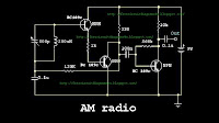
AM Receiver


This is so useful circuit for you. Because At present we have to face lots of difficulties because of not having some ICs such as ZN414 IC in the market.So we have designed this circuit to build that circuit easily.


parts

Q1 (b) 1.31V

Q2 (b) 0.71V

Q2 (c) 1.34V

Q3 (b) 0.62V

Q3 (c) 3.87V

Monday, October 26, 2009

Hold The Phone With Music


This is so useful circuit for us Because If our caller is in hold on position we can allow them to listen a music.When you want to operate this circuit you can hold on your phone and switch on the S1. The RED wire from the phone jack is typically positive and the GREEN wire is negative or ground.


Sunday, October 25, 2009

12VDC Fluorescent Lamp circuit


This circuit is so impotent circuit for the car owners.Most of time they have asked about a circuit like this (12v Fluorescent lamp)so you can attach a colorful fluorescent lamp like this for your vehicle.


Parts:


C1 100uf 25V Electrolytic Capacitor

C2,C3 0.01uf 25V Ceramic Disc Capacitor

Q1 IRF510 MOSFET

U1 TLC555 Timer IC

T1 6V 300mA Transformer

LAMP 4W Fluorescent Lamp

MISC Board, Wire, Heatsink For Q1

C4 0.01uf 1KV Ceramic Disc Capacitor

R1 1K 1/4W Resistor

R2 2.7K 1/4W Resistor


note

1. Attach a heat sink for Q1
2.
A 240V to 10V transformer will work better then the one in the parts list. The problem is that they are hard to find.

Friday, October 23, 2009

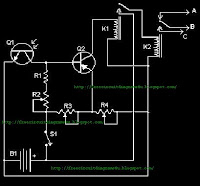
Automatic Headlight Brightness Switch Circuit


When you drive on the way most of time, you can see some drivers drive their vehicles with their powerful head lights.As a result of it we can't drive our vehicles because at that time we become blind,Some times it causes for various road accidents.So I have introduce a new circuit to switch your high beam to low beam automatically.when a vehicle comes in front of you automatically your head lights go to dim position.


Parts:

R1 5K 1/4W Resistor

R2, R3, R4 5K Pot

K1 Low Current 12V SPST Relay

K2 High Current 12V SPDT Relay

S1 SPST Switch

B1 Car Battery

MISC Case, wire, board, knobs for pots

Q1 NPN Phototransistor

Q2 2N3906 PNP Transistor


Note

1.S1 can on and off the circuit.

2. B1 is, certainly, in the car already.

3. Connection A goes to the high beam circuit, B goes to the headlight switch common and C connects to the low beam circuit.

Monday, October 19, 2009

Telephone line monitoring circuit


This is very useful circuit for all because you can record telephone conversations automatically.What you have to do is connecting this unit to the phone line,Recorders remote control jack and to your tape recorder's microphone input.when the voltage of the line drops 5v or less it automatically starts to record.


Parts

R2 1.5K 1/4 W Resistor

R4 33K 1/4 W Resistor
C1 0.22uF 150 Volt Capacitor
R1 270K 1/4 W Resistor
Q1, Q2 2N4954 NPN Transistor
D1 1N645 Diode
R3 68K 1/4 W Resistor
MISC Wire, Plugs To Match Jacks On Recorder, Board, Phone Plug

Saturday, October 17, 2009

LED Torch


We can see when we use torches we can't use it for long time but here I have mention a circuit. it shows the way of using a long life L.E.D torch.It gives 80 times longer service.Than normal Torch.


Note

# If you want to use different voltage you can do these modifications.

# Change R3 values as follows, according to the power.

9V - 470 Ohm
12V - 560 Ohm

Friday, October 16, 2009

Long range AM transmitter Circuit


This is a long range transmitter.This circuit can send signals up to 2km.So that you have to use 1m copper wire.The power of this transmitter has been increased by usin two transistors. When you use this transmitter do give power with out connecting the antenna.Because it will burn your transistors.


Note


# The transformer T1 can be a general purpose audio driver transformer seen in transistor radios.

# The inductor L1 can be made by making 56 turns of 365 WG enameled copper wire on a 1 cm former.

# Inductor L2 can be a 10 mH general purpose radio frequency choke.

# The circuit can be powered from a 9V PP3 battery.

Single chip metal detector circuit


This circuit is a Single chip metal detector.Actually we can use this one to detect metals.Specially,I think you have seen some army soldiers keep some thing to detect metals.That equipment has been made through this circuit.so you also can use this to detect metals even bombs


Note

# The IC must be mounted on a holder.

# The switch S1 can be a slide type ON/OFF switch.

# The POT R1 can be used to adjust the sensitivity of the circuit.

Zero degree Celsius alarm


This is a circuit of Zero degree Celsius alarm . this is very useful circuit for all.Because we all can get different uses from this circuit.When you fix this circuit You have to face to a problem it is none but the power supply.Here I have given a power supply so you can avoid that problem.


Power supply


Thursday, October 15, 2009

Light activated switch circuit


This circuit is well important circuit for us because We can get lots of advantages through this circuit.When the light puts on L.D.R the circuit activates.So you can use this one as you morning alarm or you can use this one for your robot.


Note


# You can use either a 12 V battery or a well regulated & filtered 12V DC mains operated power supply.


# The pin 5&6 (Balance & Balance/Strobe ) of IC LM311 are shorted to minimize the chance of oscillations.

FM Antenna Booster Circuit Diagram


This is a FM antenna booster circuit diagram.This helps you to get clear fm signals to your radio.The well important thing of this circuit is spending less money to build up this.Try this...


Monday, October 12, 2009

Infra red switch circuit


This is so impotent circuit for us because We can operate this circuit by using any kind of IR remotes.To operate the relay any buttons must be pressed two seconds.and to reset press any button and hold it for a moment.Try this....


Note

# Use 12 v to power

# Build this circuit on a copper Board

Sunday, October 11, 2009

Free Single Chip FM Transmitter circuit diagram


This is a transmitter circuit has only a chip.You can use this circuit to do various things.This circuit has good power.so you can listen music by attaching this circuit to your computer or by attaching to your cd player you can listen music when you stay in your garden.The FM transmitter circuit here works in the broadcast band 88 to 108MHz,And this one has the power of -21dBm.so I suppose you will be able to get good result.


Note


# You can give 3v to 5v for this circuit
# Build this one on a copper board.

LED Flasher (Multivariater) Circuit


This is very simple circuit.So beginners can fix this circuit easily.There are two LEDs.The LEDs blink one by one.Then If you want to control the time of LEDs.you can do that by changing the value of capacitors.So beginners this is a wonderful opportunity to you.


I have done several test to use this one as a pulse generator those test were succeeded so you also can use this one as a pulse generator.


Note


# use 9v batty to power this

Saturday, October 10, 2009

simple dynamic microphone amplifier


This is a circuit Which can use as a dynamic microphone amplifier.This circuit can handle 50Hz to 100Khz signals.


Note

# This circuit is designed for use with 200 Ohm dynamic microphones. For usage with low impedance microphones, the value of R3 must be increased to around 47o Ohms and

# C1 must be decreased to around 2.2uF.

6W amplifier with TA7222AP


This is a very useful amplifier.this can give 6w out put.And this circuit can be operated with 12v power.so I know this is a good news for the vehicle owners.Use 4 ohms Speakers.


Note

# Use 12V DC to power the circuit.
# The IC must be heat sinked.

Friday, October 09, 2009

Wireless mains voltage tester.


You can use this to test whether the electricity is available in the line or not just attach a wire for the end of senser then you can get signals easily 1 feet is enough


note

Use 9V PP3 battery for powering the circuit.

Voice modulator circuit


This is a fantyastic circuit for you because you can make various voices through this circuit you can make 7 voices.so try on this and have a fun


Push button switch S1 can be used to activate Vibrato mode and push button switch S4 can be used to activate the Robot mode.S2 and S3 can be used for the upward and downward frequency stepping .


Note


# S5 can be a miniature ON/OFF switch.

# Switches S1 to S4 can be miniature push button switches.

# Do not give more than 4.5v to the circuit.


8 function christmas lamp


This is a gift for you for the on coming Christmas.This is a 8 function christmas lamp so yopu can use this to decorate your xmas tree or your crib.


Note

# L1 to L4 can be 230V/40W lamps.

# Heat sinks are recommended for the SCRs.

# H1 to H4 can be TYN612 SCRs.


SO Happy Christmas for you

Wednesday, October 07, 2009

12V 15A voltage regulator


Hear you can see powerful regulator.The pacification of this circuit is this one can deliver up to 15 A of current.and also it can give steady 12v current.


Notes

# The T1 can be a 230V AC primary, 18V secondary, 15A type transformer.

# If 15A Bridge is not available, make one using four RURG1520CC diodes.

3 Input mic mixer circuit


This is a three input mixer.so you can use this to play your instruments or you can use this for small theaters.so try this.I have use this one for our special meetings.Total gain of the system is around 45decibel.


Note


# All inputs and output must be connected with respect to the ground.
# A +15/-15 V DC dual power supply is needed for powering the circuit.
# Electrolytic capacitors C1, C2 and C3 must be rated 10V and other capacitors must be 30V.


Tuesday, October 06, 2009

Electronic toss circuit


This is a fun circuit.you can use this one for various games.And there are lots of games tossing is required.so use this for that


Note

#This circuit can be powered With 5v DC

Automobile turn signal circuit.


This is a circuit which can use as a sequential signal light in automobiles.so the vehicle owners can use this to modify their vehicles.


Notes.

# This circuit need 12v power so you can provide it from your vehicle.

Monday, October 05, 2009

OR AND NOR GATE SIgns


http://www.freeclipartnow.com/d/40920-1/circuit-elements.jpg
I think this signs will be so useful for the beginners who engage in electronics.Because most of them don't know the correct signs.Specially this will be a great advantage for the students who study in schools.


.
.
.
.
.
 

Thank U & Come Again.....


Search Engine Optimization and SEO Tools
Submit ExpressSearch Engine Marketing

FREE CIRCUIT DIAGRAMS 4U Copyright © 2009 REDHAT Dashboard Designed by SAER