Free Electronic Circuits,Schematic Diagram,Circuit Diagrams

Thumbnail image that says sleek button using photoshop that links to a Photoshop tutoril. free, electronic circuit, circuit diagram, circuit schematic, schematic diagram, electronic diagram, audio, amplifier, power supply, guitar effect, current loop, current limiter, video, receiver, transmitter, transceiver, transistor, radio frequency, rf, active filters, digital, analog circuit, pwm, micro controller Free download

Free Electronic Circuits,Schematic Diagram,Circuit Diagrams

External links - Jqueryelectronics circuit,circuits,schematic diagram,circuit design,circuit diagram, circuit

Electronic Circuit,Schematic Diagram,Circuit Diagrams

External links - Jqueryelectronic circuit, circuit diagram, circuit schematic, schematic diagram, electronic diagram, audio, amplifier, power supply, guitar effect, current loop, current limiter, video, receiver, transmitter, transceiver, transistor, radio frequency, rf, active filters, digital, analog circuit, pwm, micro controller Free download

Best Song Lyrics Collection

External links - JqueryFind The Music Lyrics To Any Song! It's Free DAILY UPDATED! One of the largest,most accurate, browsable and searchable song lyrics source on the net. lyric, lyrics, song, music, song lyrics, music lyrics

Tuesday, September 08, 2009

Medium power FM transmitter circuit


This is the circuit diagram of a moderate power FM transmitter circuit employing two transistors.The voice signals picked by the microphone will be amplified by the transistor Q1.The second transistor is wired as an oscillator operating in the FM band.The output of T1 is given to the base of T2.T2 performs the modulation also.The tank circuit comprising of components L1 and C6 determines the frequency of the signal, and can be varied by adjusting C6.The capacitor C7 couples the FM signal to the antenna.
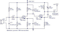


Notes.

* You can assemble the circuit on a general purpose PCB.
* The circuit can be powered from a9V PP3 battery.
* The Antenna A1 can be a 1M long wire.
* The inductor L1 can be made by making 6 turns of 0.8mm enameled copper wire on a 5.5mm diameter/4.5mm length plastic former.
* With a matching antenna and proper tuning this transmitter can have range upto 100meters.

0 comments:

Post a Comment | Feed

Post a Comment


.
.
.
.
.
 

Thank U & Come Again.....


Search Engine Optimization and SEO Tools
Submit ExpressSearch Engine Marketing

FREE CIRCUIT DIAGRAMS 4U Copyright © 2009 REDHAT Dashboard Designed by SAER