Free Electronic Circuits,Schematic Diagram,Circuit Diagrams

Thumbnail image that says sleek button using photoshop that links to a Photoshop tutoril. free, electronic circuit, circuit diagram, circuit schematic, schematic diagram, electronic diagram, audio, amplifier, power supply, guitar effect, current loop, current limiter, video, receiver, transmitter, transceiver, transistor, radio frequency, rf, active filters, digital, analog circuit, pwm, micro controller Free download

Free Electronic Circuits,Schematic Diagram,Circuit Diagrams

External links - Jqueryelectronics circuit,circuits,schematic diagram,circuit design,circuit diagram, circuit

Electronic Circuit,Schematic Diagram,Circuit Diagrams

External links - Jqueryelectronic circuit, circuit diagram, circuit schematic, schematic diagram, electronic diagram, audio, amplifier, power supply, guitar effect, current loop, current limiter, video, receiver, transmitter, transceiver, transistor, radio frequency, rf, active filters, digital, analog circuit, pwm, micro controller Free download

Best Song Lyrics Collection

External links - JqueryFind The Music Lyrics To Any Song! It's Free DAILY UPDATED! One of the largest,most accurate, browsable and searchable song lyrics source on the net. lyric, lyrics, song, music, song lyrics, music lyrics

Wednesday, September 30, 2009

6W amplifier using TA7222AP


This is a good news for the car owners because this amp works with 12v.TDA7222AP is an excellent integrated audio amplifier which can deliver 5.8W to a 4 Ohms load


Notes.

* The circuit can be assembled on a Vero board.
* Use 12V DC for powering the circuit.
* The IC must be heatsinked.
* Speaker can be a 4 ohms one.
* For optimum performance input and output must be separately grounded.

Stereo balance indicator


You can use this circuit to modify your own amplifier.this shows the out put sound level.you can use this one for various things.


Notes.

* The circuit can be assembled on a Vero board.
* Use 9V DC for powering the circuit.
* Mount IC1 on a holder.
* C1 ,C2 and C3 must be rated at least 6V.

Fire Alarm


Here we have used some what different concept.normally we use LDR for light sensitive circuits.but here we use this LDR to detect smoke.I will explain you, how we can do this.first of all we should keep in the kitchen or in a place where the fire can be occurred then keep LDR and the bulb face to face and let smoke to pass between the LDR and the light.when the smoke passes that area it begins to make a sound


Humidity tester


This is a humidity tester.If you are conducting a flower nursery you can use this circuit to know the humidity of your green houses.and we can attach alarms for this.then it will show you that the humidity has changed so you can use this circuit to grow your plants under a control situation


Notes.

* The probes can be anything like iron nail.pin paper clip etc.
* To calibrate the circuit for particular density,insert the two probes to the required material and adjust R3 so that the LED glows.The LED will glow whenever the humidity of the testing sample becomes equal to this humidity level.
* A 3V battery can be used to power the circuit.
* Another general purpose NPN transistors like BC107,BC148,2N2222 etc can be also used for Q1.

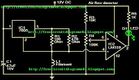
Air flow detector circuit.


If you have industry at that situation this would be so useful circuit.we use this circuit to knowe whether air is flowing or not.so you can use this one for your car also (recently we hope to introduce HHO technology so at that situation you can use this one to indicate the air flowing.


Tuesday, September 29, 2009

Electronic siren circuit


This is an electronic siren.you can use this one to your security systems or burglar alarms.so be creative then you can build up a fantastic creation.


* A 12 V battery or a a well regulated 12V DC power supply can be used to power the circuit.
* Assemble the circuit on a good quality PCB or common board.
* The switch S1 can be used to activate the alarm.
* The switch S2 can be used as a power switch.
* You can experiment on the tone of alarm by using different values for C2 and R8.

Power megaphone circuit


This is a power mega phone .you can use this to address people in various situation such as when you play in a aground,in a public meeting(small one) etc..so this is so useful one.


Notes.

* The circuit can be powered from a 12V battery or 12V DC power supply.
* The POT R1 can be adjusted to obtain maximum volume with minimum distortion.
* It will be always better to mount the transistors on heat sink.


Thermostat


This is simple electronic thermostat using IC LM56.by using this one you can know whether the temperature of the equipment that you use is over heating or not.so this is very useful equipment to save your electrical equipments from over heating.


Two stable temperature trip points (VT1 and VT2) are created by dividing the LM56’s 1.250V internal voltage reference using 3 external resistors (R1, R2 and R3). There are two digital outputs for LM56 .Output1 becomes LOW when the temperature increases above T1 and goes HIGH when the temperature decreases below (T1±Hysteresis Temperature). In the same way, Output2 becomes LOW when the temperature goes above T2 and goes HIGH when the temperature goes below (T2±Hysteresis Temperature).


VT1 = 1.250V x (R1)/ (R1 + R2 + R3)
VT2 = 1.250V x (R1 + R2)/ (R1 + R2 + R3)
where:
(R1 + R2 + R3) = 27 k Ohms and
VT1 or T2 = [6.20 mV/degree Celsius x T] = 395 mV therefore:
R1 = VT1/ (1.25V) x 27 k Ohms
R2 = (VT2/ (1.25V) x 27 k Ohms) – R1
R3 = 27 k Ohms – R1 – R2

Monday, September 28, 2009

4W Fluorescent lamp driver.


This is a 4W fluorescent lamp driver.we can operate this with 12 v battery.so I suppose you can attach this one for your vehicle even. on the other hand you can use this one as an emergency lamp.so try on this be creative to get the maximum harvest.


Notes.

* Assemble the circuit on a general purpose PCB.
* The IC 1 must be mounted on a holder.
* Use heat sink for transistor Q1.
* Use a 3 V primary , 230 V secondary, 5W transformer for T1.
* Power the circuit from a 12V battery or 12V DC power supply.
* The L1 can be a 6 inch, 4W fluorescent lamp.

3 Band graphic equalizer circuit


This is a 3 brand graphic equalizer circuit. By using this circuit you will be able to get the maximum advantage.The high input impedance of the IC makes this circuit compatible with most of the audio signal sources.The filter network can produce a +/- 20 dB enhancement or cut on the three frequency bands 50Hz,1KHz and 10KHz.POTs R1, R2 and R3 can be used for adjusting the gain of the different bands.


NOTICE:

# The Circuit can be powered from anything between 6 to 30V DC.
# I am using 12V here.
# Increasing supply voltage will of course increase the gain.
# The IC must be mounted on a holder.
# The electrolytic capacitors must be rated higher than the supply voltage.

Blown fuse indicator circuit


This is very useful circuit because most of time we all have to face lots of troubles if the fuse has blown away so this is the answer for that by using this circuit you can recognize whether fuse has blown or not because the LED indicates it.


*1N4007 for D1,D2,D3 and D4

*230V primary,12V secondary ,2A step-down transformer for T1

*2A fuse

*1000uF/25V capacitor for C1.


NOTICE


# The circuit will not work if the load is not connected.
# A highly resistive load may also impart the working of the circuit.

Sunday, September 27, 2009

5V power supply with overvoltage protection.


Over voltage has become a problem for countries like us so this is a best solution for that this releases 5v


Notes.

* If 1A Bridge is not available, make one using four 1N4007 diodes.
* The trip voltage can be varied by varying the values of D2 and R2.
* All capacitors must be rated at least 25V.
* The transformer T1 can be a 230 V AC primary, 12v secondary, 2A step-down transformer.
* Assemble the circuit on a general purpose PCB.


Water activated musical bell


This circuit gives a sound when water or conducting liquid touches with the sensors which are provided (A,B).by using this circuit you can get lots of advantages as an example you can attach this one for your water tank and when it over flows you can know it before be creative then you can make lots of things with this.


Notes.

* Two insulated aluminum wires can be used as the sensor.
* The IC1 must be mounted on an IC holder.
* The speaker can be a 8 Ohm, ½ W tweeter.
* Assemble the circuit on a good quality PCB or common board.

Sound operated flip flop.


This is a circuit which the status of the output pins of a Flip Flop IC can be toggled by using sound. A condenser microphone is used for picking up the sound.


The first two opamps in the IC1 LM 324 is used to amplify the sound picked by the condenser microphone. The third opamp inside LM 324 is wired as a level detector. When ever the voltage produced due to sound have a level more than that of the reference voltage at pin 5 of the third opamp, its output (pin 7) goes high, triggering the flip flop IC1 CD 4027.As a result the state of the output pins of CD 4027 ( pin 1 & pin 2) toggles for each burst of sound


Notes.

* The circuit can be powered from three 1.5 V cells in series.
* The ICs must be mounted on holders.
* The mic M1 is a condenser mic.
* The sensitivity of the circuit can be adjusted by varying the preset R9.
* Assemble the circuit on a good quality PCB.
* All capacitors must be rated 10V.

trailing switch.


Trailing switch is an equipment which gives the current to the unit which we want to operate if control socket is switched on. For example, let’s connect a motor is connected to the control socket and a lamp is connected at the trailing socket. The lamp will glow only when the motor is running.


When the load connected at the control circuit is switched on, the load current flows through the diodes and as a result there will a voltage drop across the diodes. This voltage drop is sufficient enough to switch on the sensitive triac T1 and the equipments connected at the trailing sockets gets power supply. The components R2 and C1 forms a snubber circuit which protects the triac from transient fluctuations.

Almost all equipments like motors, drills, blenders, fan, old TV, radio, amplifiers etc can be connected at the control socket. In case of modern TV, computers, amplifiers, etc the power switch does not completely isolate the equipment and the equipment will draw a small amount of current in the standby mode which is sufficient enough to trigger the triac . Such equipments cannot be used on the control socket because it makes the trailing equipments ON even if the control equipment is OFF.


Notes.

* Assemble the circuit on a good quality PCB.
* The triac T1 must be a 600V, 8A, high sensitive gate type like TIC 225M.
* Maxim load that can be connected at the trailing socket is 1000W.
* Fit the triac with a heat sink.
* Take at most care while handling this circuit as it is connected to 230V AC.


LED multivibrator


This is a fantastic circuit because lots of beginners select this one as their first circuit. by using this one you can do lots of things that means you can make pulse generators even.Here two LEDs are blinking one by one.


This can be operated by using 3v battery

parts:-


* Q1 and Q2 = C828
*C1 and C2 = 100uf

*R1 and R4= 47k
*R2 and R3= 33k
*LED=2 co lour leds


Hear if you want to add more leds you can use D400 instead of C828 then you can add leds up to 12.

Saturday, September 26, 2009

Battery charger circuit using SCR.


A simple battery charger based on SCR is shown here.Here the SCR rectifies the AC mains voltage to charge the battery.When the battery connected to the charger gets discharged the battery voltage gets dropped.


This inhibits the forward biasing voltage from reaching the base of the transistor Q1 through R4 and D2.This switches off the transistor.When the transistor is turned OFF,the gate of SCR (H1) gets the triggering voltage via R1 & D3.This makes the SCR to conduct and it starts to rectify the AC input voltage.The rectified voltage is given to the battery through the resistor R6(5W).This starts charging of the battery.
When the battery is completely charged the base of Q1 gets the forward bias signal through the voltage divider circuit made of R3,R4,R5 and D2.This turns the transistor ON.When the Q1 is turned ON the trigger voltage at the gate of SCR is cut off and the SCR is turned OFF.In this condition a very small amount of charge reaches the battery via R2 and D4 for trickle charging.Since the charging voltage is only half wave rectified ,this type of charger is suitable only for slow charging.For fast charging full wave rectified charging voltage is needed.


Notes.

* Assemble the circuit on a good quality PCB or common board.
* The transformer T1 can be 230V primary, 18V /3A secondary step down transformer.
* The voltage of the battery at which the charging should stop can be set by the POT R4.
* The battery can be connected to the charger circuit by using crocodile clips.


3 LED battery monitor circuit


This is the circuit diagram of a 3 LED bar graph type battery monitor circuit that is ideal for monitoring the voltage level of an automobile battery


When battery voltage is 11.5V or less transistor Q1 will be On and the LED D1 will be glowing.When battery voltage is between 11.5 and 13.5V, the transistor Q2 will be On and the LED D2 will be glowing.When battery voltage is above 13.5V the transistor Q3 will be On and the LED D3 will be glowing.


Notes.

* Assemble the circuit on a general purpose PCB.
* The battery to be monitored can be connected between the terminals namely A and B.
* It is always better to use LEDs of different colour.

VHF field strength meter


This is a simple and low cost wide band VHF field strength meter. The field strength is measured by converting the radio signal to DC and measuring it.


The RF signal will be picked up by the coil and rectified by the diode D1.Even a very small DC voltage is sufficient to alter the biasing of FET and it will be reflected in the meter as an indication of the presence of a radio signal. The meter can be calibrated by adjusting the preset R2 to make meter M1 read ZERO in the absence of any radio signal. This circuit is not very sensitive, but can sense radio signals from hand held FM transmitters up to a distance of few meters( ideal for theoretical demonstrations).


Notes.

* The circuit can be assembled on a general purpose PCB.
* Use a 9V PP3 battery for powering the circuit.
* Use a 250uA FSD current meter for M1.Using a lower FSD meter will improve sensitivity.
* The coil L1 can be made by making 6 turns of 20 SWG enameled copper wire on a inch plastic former.
* The antenna can be a telescopic whip antenna.

Friday, September 25, 2009

Versatile emergency lamp.


versatile emergency lamp that can be operated in two modes (flasher and dimmer). The circuit is based on the dual op-amp IC LM358.The dimmer and flasher mode can be selected by using the switch S1.


Notes.

* F1 should be a 2A fuse.
* L1 can be a 12V; 2A incandescent lamp.
* IC1 must be mounted on a holder.
* The circuit can be assembled on a Vero board.
* Use a 12V battery for powering the circuit.
* A heatsink must be fitted on transistor T2.
* S2 can be used as an ON/OFF switch.


christmas lamp


The UTC 8156 can control the four lamps in 8 modes namely waves, sequential, slo-gol, chasing/flash, slow fade, twinkle/flash, steady ON and auto scan. Control signals for controlling the lamps will be available at pin 12 to pin 15 of the IC. SCRs are used to drive the lamps according to these control signals.


Notes. * The circuit can be assembled on a Vero board. * L1 to L4 can be 230V/40W lamps. * H1 to H4 can be TYN612 SCRs. * Heat sinks are recommended for the SCRs. * IC1 must be mounted on a holder. * If 1A bridge is not available, make one using four 1N4007 diodes. * S1 can be an 8 through rotary type selector switch. * S1 can be used to select the modes.

Thursday, September 24, 2009

60W inverter using transistors


Here is the circuit diagram of a fully transistorized inverter that can drive up to 60W loads. Transistors Q1 and Q2 forms a 50Hz astable multivibrator.


The output from the collector of Q2 is connected to the input of the Darlington pair formed by Q3 and Q4.Similarly the output of Q1 is coupled to the input of the pair Q5 and Q6. The output from the Darlington pairs drive the final output transistors Q7 and Q8 which are wired in the push pull configuration to drive the output transformer.


Notes.

* The circuit can be assembled on a vero board.
* T1 can be a 230V primary to 9-0-9V, 6A secondary transformer.
* Transistors Q4, Q6, Q7 and Q8 must be fitted with heat sinks.
* Use a 12V, 7Ah battery for powering the inverter.
* Slight adjustments can be made on the value of R3 and R4 to get exact 50Hz output.

Wednesday, September 23, 2009

Simple Telephone Security Device


This circuit continuously checks the tel. lines and when it detects a misuse, it sounds an alarm. Additionally it transmits a loud disturbing tone through the telephone lines to prevent further misuse. The circuit does not require any external power supply.


When the switch S1 is at the on position, the line voltage at the output of the rectifier diodes is approximately 48V which is enough to exceed the zener's (D5) break down voltage. So the T2 gets forward biassed. As a result the base of T1 is grounded and the remaining part of the circuit doesn't get any supply. In this condition, circuit draws so small current that is negligible and does not effect the normal operation of the telephone line.

When handset of any telephone connected to the line is lifted, the line voltage drops to 10V so T2 is switched off and T1 gets in forward biassed mode. The astable multivibrator circuitry starts oscillating and the speaker starts sounding. The output of the astable multivibrator is also connected to the base of T1 so a loud sound is heard in the ear piece of the unauthorized telephone instrument.

Scoring game circuit.


A simple scoring game circuit that can be used for all occasions when a dice is needed.The circuit is based on a NE555 timer,a 74LS192 counter,a74LS247 decoder and a & segment LED display.


The timer IC1 will produce the clock for the counter IC(IC2) whose frequency is determined by R1 and C2.When S2 is pressed the IC2 will count in up mode and when S3 is pressed the IC2 will count in down mode.The IC 3 will decode the count to display it on the seven segment LED display .Thats about the working of the circuit.The circuit is designed strictly sticking on to the basics of counters and is a good one for beginners.There is nothing big deal.


Notes.

* To play the game switch the power ON and press S1 to reset the counter.
* Now press S2 or S3 and release .The IC2 will hold the last count .Now press S4 to see the score on display.That’s your score.Now the second person can try.
* Each time one tries, he should press the S1 to reset the count and then press S2 or S3 and then S4 to see the score.
* Circuit can be powered from a 9V radio cell or a 9V regulated DC power supply .

Organ circuit


Here is the circuit diagram of a simple yet interesting mini organ based on UJT 2N 4891( Q1).


The circuit is based on a UJT oscillator who’s frequency is determined by the Presets R6 to R13(one at a time) and capacitor C2.The transistor Q2 drives the speaker to produce reasonable sound output.For each pushbutton press the corresponding preset will be added to the circuit ,and the UJT oscillates in a frequency proportional to it.This frequency will be amplified by the transistor to produce the sound at the speakers.A 9V battery or 9V DC power supply can be used to power the circuit.

Notes.

* Power up the circuit and adjust the presets (R6 to R 13) to get the desired tune at the output for the press of corresponding push button.

* Preset R1 (5K) can be used as a volume control.


* You can also try different values for C2 get the desired tunes.


* All capacitors are of ceramic type.


.
.
.
.
.
 

Thank U & Come Again.....


Search Engine Optimization and SEO Tools
Submit ExpressSearch Engine Marketing

FREE CIRCUIT DIAGRAMS 4U Copyright © 2009 REDHAT Dashboard Designed by SAER